You may have heard that old flash guns and heads shouldn’t be used with modern DSLRs, because their sync voltage (i.e. the voltage across the hot shoe or sync connector) can be very high. Tens of volts on the sync connections were common, but in some cases the voltages were in the hundreds. To find out the voltage level of an old flash unit a good place to start is here: http://www.botzilla.com/photo/strobeVolts.html, preferably followed by digging out your voltmeter and checking it for yourself.
Back in the day, cameras triggered their flashes by mechanically shorting the flash connections, probably using some sort of relay based circuit. Nowadays everything is done electronically, and the voltage a camera is safe to work with depends on what manner of electronics are built into the camera. As a Canon user the general advice seems to be not to use flashes with a sync voltage greater than 6 volts for hot shoe connected units, although for Canon models with built in sync sockets the allowable voltage (on the sync socket, not the hot shoe) appears to be higher.
So if you’ve got old flash units kicking about that you might still want to use with your DSLR using a wired connecton, the best way to ensure the camera doesn’t get fried is by using a safe sync unit. You can buy these for a price, but where’s the fun in that? It only takes a few (cheap) components to make your own, and as long as you know which end of a soldering iron to hold it’s not a very challenging build.
For this project I’m aiming to build a unit that:
- doesn’t need a battery (ie it takes its power from the flash unit), and
- works with a flash unit with a sync voltage of less than 30 volts.
As far as the second requirement is concerned, since the circuit works by charging a capacitor from the voltage on the flash unit’s hot shoe via an inline resistor, if you try to make a unit that will work with every flash it’s going to recycle very slowly when it’s used with a low-ish voltage flash. (more detailed explanation later for those with an electronics background)
Parts List
Quite a short list for this build:
- Veroboard – very small piece!
- Triac – 2N6073A
- Zener diode (I used 5.1 volts to be super safe, but a 5.6 volt should be fine)
- Diode – 1N4004
- Signal diode – 1N914 (or 1N4148)
- Resistors – 33kΩ and 33Ω
- Capacitor – 470nF
- Kood cold shoe to PC-sync socket adapter
- Small project box (mine was 34 x 24 x 16mm, but it was a pretty tight fit and getting a slightly bigger one would have made assembling the unit easier)
- A few pieces of wire to connect it all up – it’s worth using the silicone type as it’s very fexible.
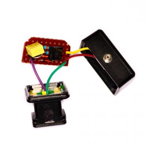
The first task is to strip down the cold shoe adapter to remove the sync socket – straight out of the packet the adapter comes with the sync socket wired straight to the hot shoe, but we’re going to break that connection and put our circuit between them. With my cold shoe the metal shoe mount can be removed by taking out two small screws from the top, and the internals can be accessed by removing three screws from the bottom. Here’s what it looked like before and after taking it apart:


When the bottom plate has been removed, along with the hot shoe contact and spring, the sync socket itself can be slid out of the side of the unit. Once that’s done, unscrew the centre pin from the sync socket and remove the tag, then cut the round end off (the tag), solder a wire to the right angled section and screw the centre pin back into the socket with this part of the tag attached. Now solder a second wire to back of the body of the socket. These two wires will be connected to the output side of the safe sync circuit when it all gets put back together. The modified socket should look something like this:

That’s the connections for the output side of the circuit sorted, so now for the input side. Solder a wire to the back of the round part of the tag that was cut off previously, and solder another wire to the back of the hot shoe ground contact (opposite the open end). These two wires will provide the trigger connection from the camera’s hot shoe.
Drill two small holes through the top of the adapter block: the first between the screw holes for mounting the cold shoe, and the second just inboard of the slot the that the sync socket used to fit in on the back of the unit. These will be used to bring the sync and ground wires from the camera’s hot shoe through to the safe sync circuit. While the drill’s out, drill a matching pair of holes in the lid of the project box, along with another pair of holes aligned with the existing cold shoe mounting holes in the adapter block. Countersink the last pair of holes, then fix the lid of the project box to the top of the adapter using the two screws that used to hold the cold shoe there.
Feed the wire soldered to the back of the round tag through the middle hole, and the one attached to the hot shoe ground contact through the back hole. Slide a small piece of plastic sheet cut to the same shape as the original sync socket backplate into the slot in the back of the adapter, then reassemble the spring, contacts and base of the adapter and fix with the original three screws.
One final bit of work with the drill is to make a hole in the side of the project box that matches the size of the collar at the housing end of the sync socket – it was 5mm diameter for my socket. Glue the sync socket into the newly drilled hole in the side of the project box using 2-part epoxy, or similar. Now you should have a block that can be plugged into a camera’s hot shoe that has two input wires and the box with two output wires – so thats the unit ready to get the electronics added.
The circuit diagram for the unit looks like this:

Assemble it on the small piece of veroboard and connect the wires from the hot shoe and the sync socket. It’s worth giving it a quick test before shoe-horning it into the project box and trying it out for real.
How it works: when a flash unit is connected to the adapter and turned on, the voltage across the flash unit’s sync input contacts causes a current to flow through the 33kΩ resistor and the 1N4004 diode to charge the capacitor. The maximum voltage across the capacitor and the 1N914 signal diode is limited to 5.1 Volts by the zener diode: once the voltage across the zener reaches that, current flows through the zener rather than charging the capacitor any further.
The charging current is limited by the 33kΩ resistor, so with this resistor value the unit is suitable for use with flashes with a relatively low sync voltage (say up to about 40 Volts). If you want to use it with a flash with a high voltage (the 2N6073A can switch up to 400V), the value of the resistor needs to be increased significantly, to several MΩ.
When the capacitor is charged, shorting out the zener diode by closing the flash contacts in the camera makes the capacitor discharge through the triac gate circuit and the 33Ω resistor, which is there to limit the current flow through the camera’s sync cicuit, and also to lengthen the capacitor’s discharge time to ensure the triac turns on. The current flowing through the triac’s gate makes it turn on, shorting out the flash’s contacts and triggering it to flash.

That’s about it: the seven component safe sync circuit. I think that’s just about as simple as you can make one of these units – correct me if I’m wrong.